I Almost Killed redstone.university Editing the Figures by Hand
Redstone University · rendered figure
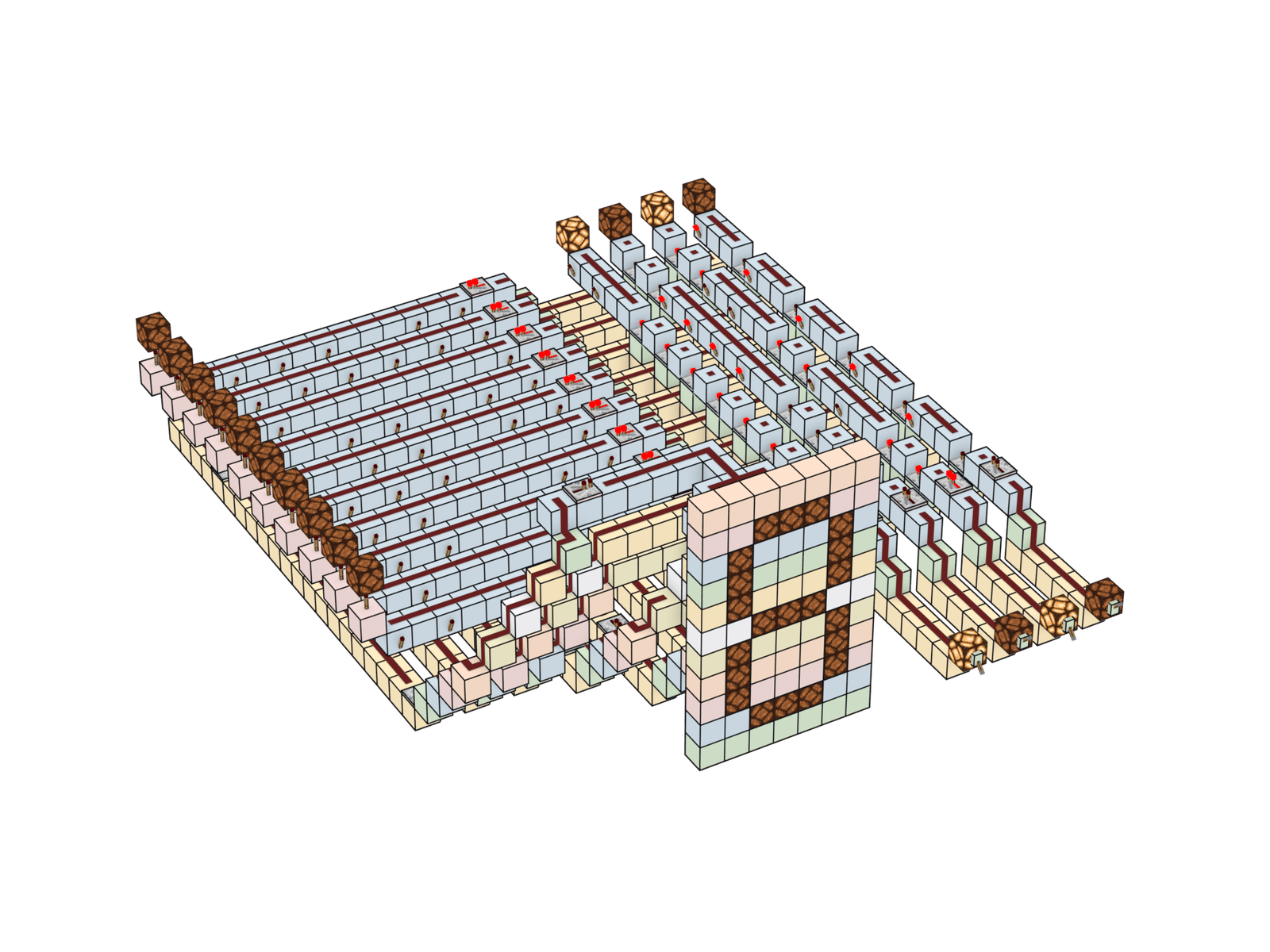
Redstone University is 4 parts, 13 modules, 0 prerequisites, and 1 working CPU, built inside Minecraft from the game’s own redstone dust, repeaters, and pistons. The pitch is that you learn how a computer works by standing inside one. Follow the dust correctly and you’re inside a decoder, watching power route down one address line instead of the others. It’s the Magic School Bus pitch, pointed at a CPU instead of Arnold’s colon.
The course teaches almost every circuit twice: once as a logic diagram, the way a textbook would draw it, and once as the actual redstone build you walk through. Two figures per concept, both clean enough to print, and both looking like they came from the same book. For most of this project’s life I made all of them by hand, and that stretch was miserable in a specific, instructive way. It also came closer to ending the project than anything the redstone ever threw at me. Now a JSON file and one command make them, and they come out better than anything I edited myself. This post is mostly me wanting to show them off.
The part where I did it by hand
Two kinds of figure. Both were made by hand, and both hurt.
The logic diagrams started in CircuitVerse, which is great for building and simulating circuits. Exporting them is another story: the SVG comes out with wires drawn as raw diagonals, gates filled however CircuitVerse feels like filling them, and connection dots scattered wherever the graph happened to route. So I’d open each export in Figma and clean it by hand: drag every diagonal wire into a right-angle route, recolor the whole thing to my palette, nudge each gate lead until it met the gate flush, delete the stray junction dots. Dozens of diagrams, anywhere from fifteen to forty-five minutes apiece.
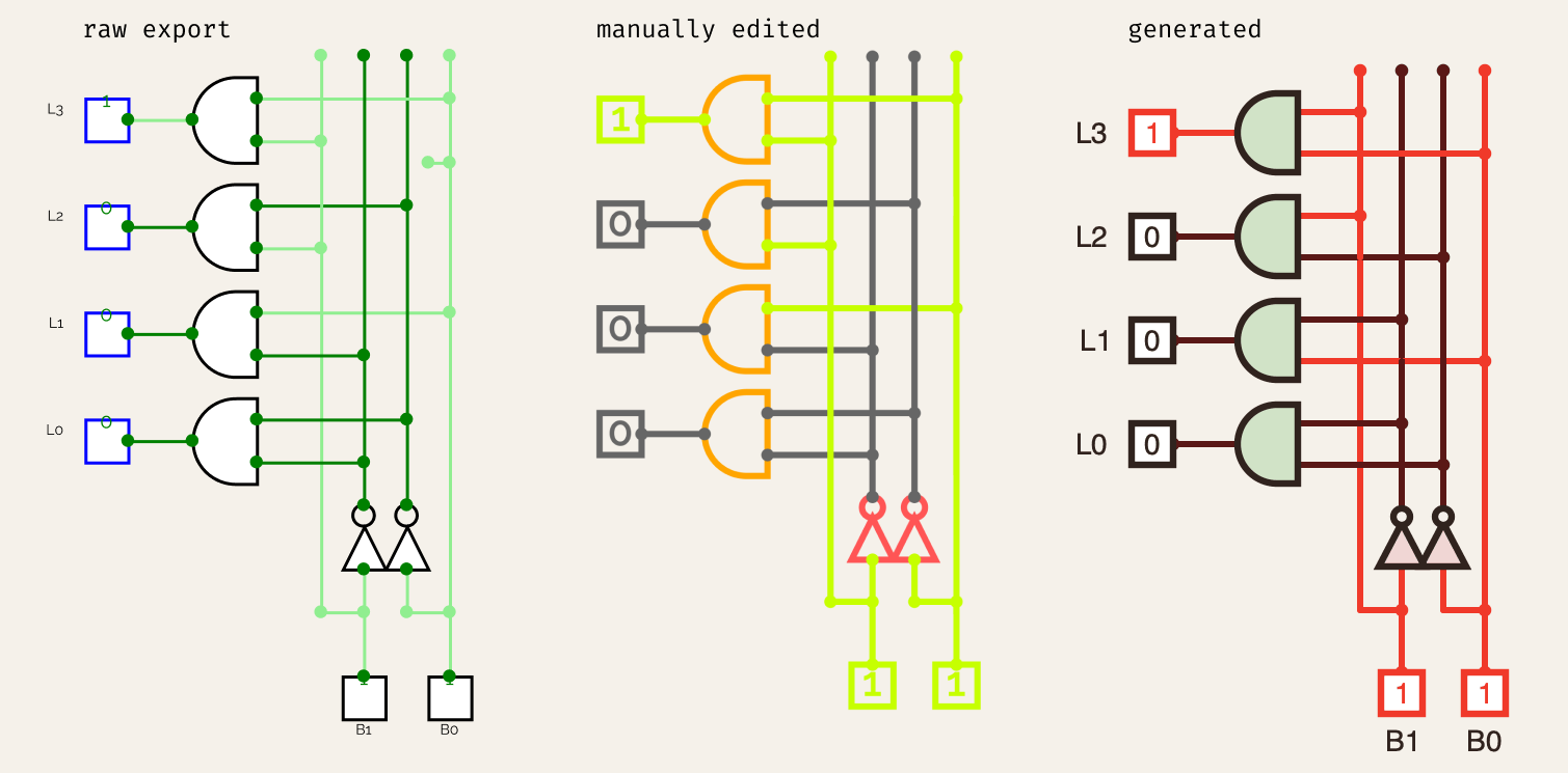
.cv file for free.That would’ve been a one-time tax I could live with, except I kept changing the palette. The course has a particular look I was still dialing in, and every time I touched the colors, every diagram in the course was wrong again and had to be redone by hand. What finally broke me was wanting the site to have both a light theme and a dark theme, because two themes means every figure exists twice, and I was drowning maintaining them once. Call it the redraw tax: I was hand-maintaining a cache of thirty-some images whose source of truth sat in a file the whole time, and every palette change invalidated every one of them.
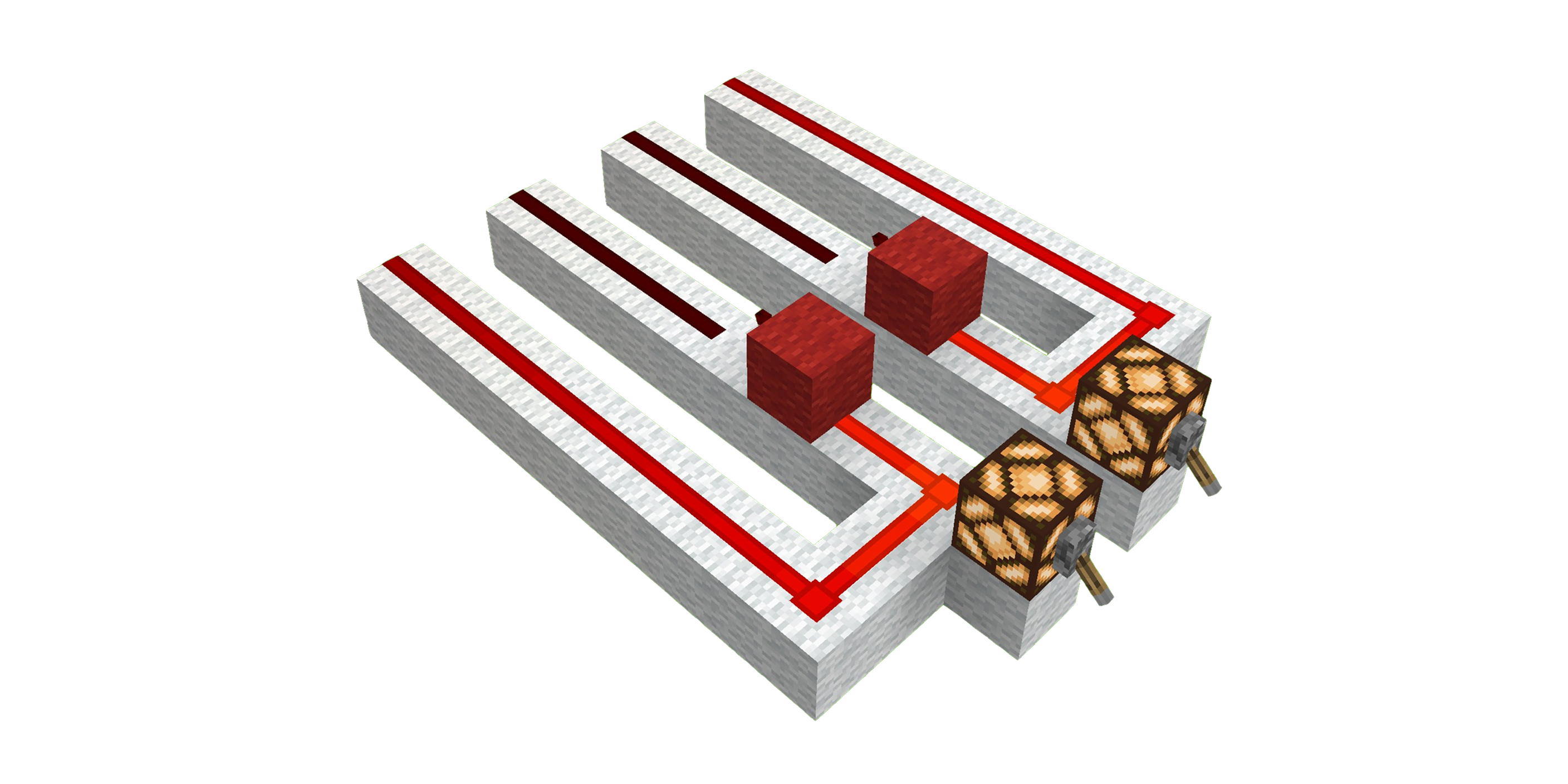
The renders were worse, because they never had a working by-hand version at all. I gave screenshots a real shot: stand in roughly the same spot relative to every build, line up the angle with the game’s camera commands, crop to something consistent. It almost sounds like a system when I say it fast. But the builds are all different sizes, so no camera distance frames a lone XOR gate and a full decoder the same way, the in-game lighting is inconsistent from shot to shot, and every screenshot drags a whole world of background terrain along with it that has to be scrubbed out by hand. Even MiEx, the tool that turns a Minecraft world into real geometry, renders solid black out of its own GUI. There was no manual path to a good render at all.
The part where I stopped drawing
Both problems had the same root: I was drawing pictures of things that already existed as data. The circuit is fully specified in the CircuitVerse project graph. The build sits block for block in the Minecraft world. A figure is just a function of one of those. So I wrote the two functions.
The diagrams now come straight from the graph. A script reads the .cv project file directly (a slightly funny extension for something this literal, like the circuit filed its own resume), treats every circuit in it as a named scope, computes the layout from the actual node positions, and Manhattan-routes the wires itself. That last part is the exact alignment work I used to do by hand in Figma, done by code, correctly, every time. It goes further than cleanup, too: it runs a real simulation of the circuit, a union-find net solve plus a gate fixpoint that keeps iterating until nothing changes, so powered wires come out red because they’re actually powered, not because I remembered to color them.
Adding a figure is now a config entry and a command. This is the real entry for the XOR diagram: it names the circuit’s scope inside the .cv file and pins the inputs to the gate’s defining case, one high, one low. The simulator works out everything that lights up from there:
"xor-gate": {
  "circuit": "XOR Gate",
  "inputs": [1, 0]
}
python3 scripts/cv_render.py "Redstone University.cv" --batch renders/diagrams.jsonNo Figma. Change the palette in one place, re-run, and every diagram in the course redraws itself in the new colors. The dark theme that started all this is still waiting on me to actually pick its palette, but that decision now costs a re-run instead of a month of Figma.
The renders come straight from the world. A second pipeline exports the build region from the Bedrock world through MiEx into USD, then hands it to Blender, running headless with no GUI and no human, a Python script driving the whole thing through Blender’s bpy API: trim the stray terrain, strip the ground, restyle every material, aim the camera off the build’s bounding box, render. The look is one I designed instead of accepted: warm parchment ground, sepia ink linework, a per-layer height tint so you can read depth, and a near-isometric telephoto camera that kills the depth-ambiguity illusion a plain orthographic view tries to slip by. It does cutaways (keep a fractional slab of the build and re-frame) and block filtering (remove dirt, etc). One command renders the whole set unattended, seventy shots at last count. The last full pass I bothered timing did 34 shots to 63 PNGs in about 14 minutes.
The rule I hold both pipelines to: every figure is generated, never hand-drawn, and you never hand-edit the output. If a figure is wrong, fix the config or the script and re-run. A hand-edit is a lie the next palette change will expose. And the two pipelines share one design system, the same palette and the same two fonts, so a logic diagram and a photo of the redstone that implements it come out looking like they belong to each other. The tie runs deeper than fonts, too: the red of a powered wire in a diagram is tuned to the glow of the rendered dust, and the gates are filled with the same pastels as the block layers they’re built from in the renders.
Which makes the honest accounting of my own job pretty short. I build the structure in Minecraft, I add the circuit to the CircuitVerse project, and I type the bounding coordinates of each render into a JSON file. The coordinates come from the one job MiEx’s GUI still has: frame the region, export, throw the black image away, and read the bounds back out of its log file. That’s the whole list. All three inputs are me declaring a source, and even the framing is just a coordinate box in a config file, no camera aimed by eye. Everything downstream generates itself. I’m fairly sure I haven’t opened an image editor for this project in weeks, and the day I wire up automatic bounds detection, the three-item job list drops to two.
The results
Here’s the part I actually wanted to get to.
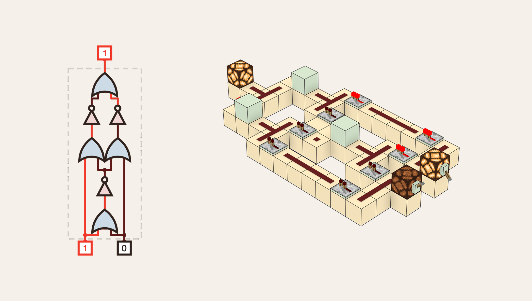
The same gate, twice: the clean schematic on the left, a render of the real redstone build that implements it on the right, same palette, same family.
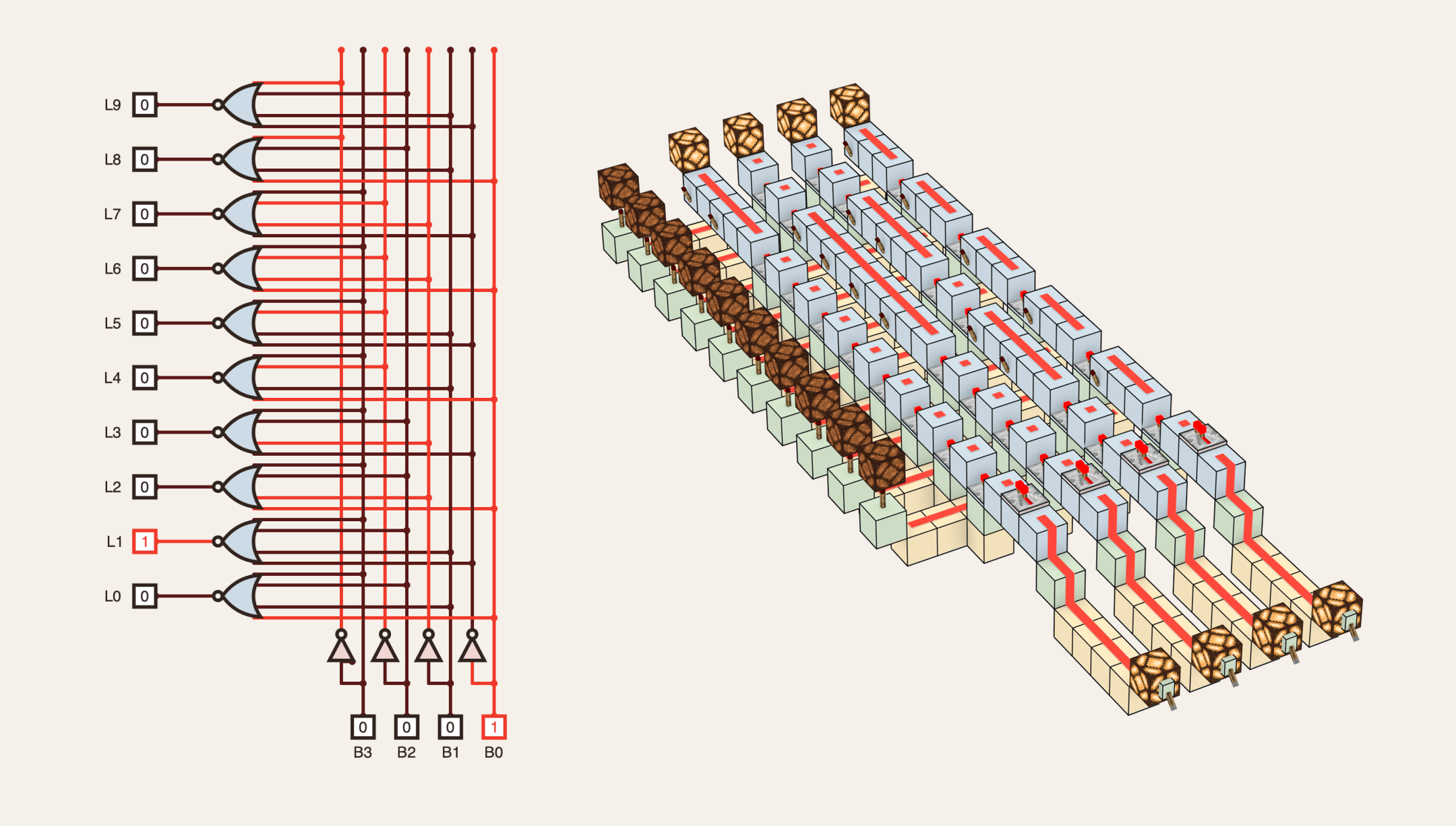
A 4-to-10 decoder, as a diagram and as the actual multi-layer build it turns into:
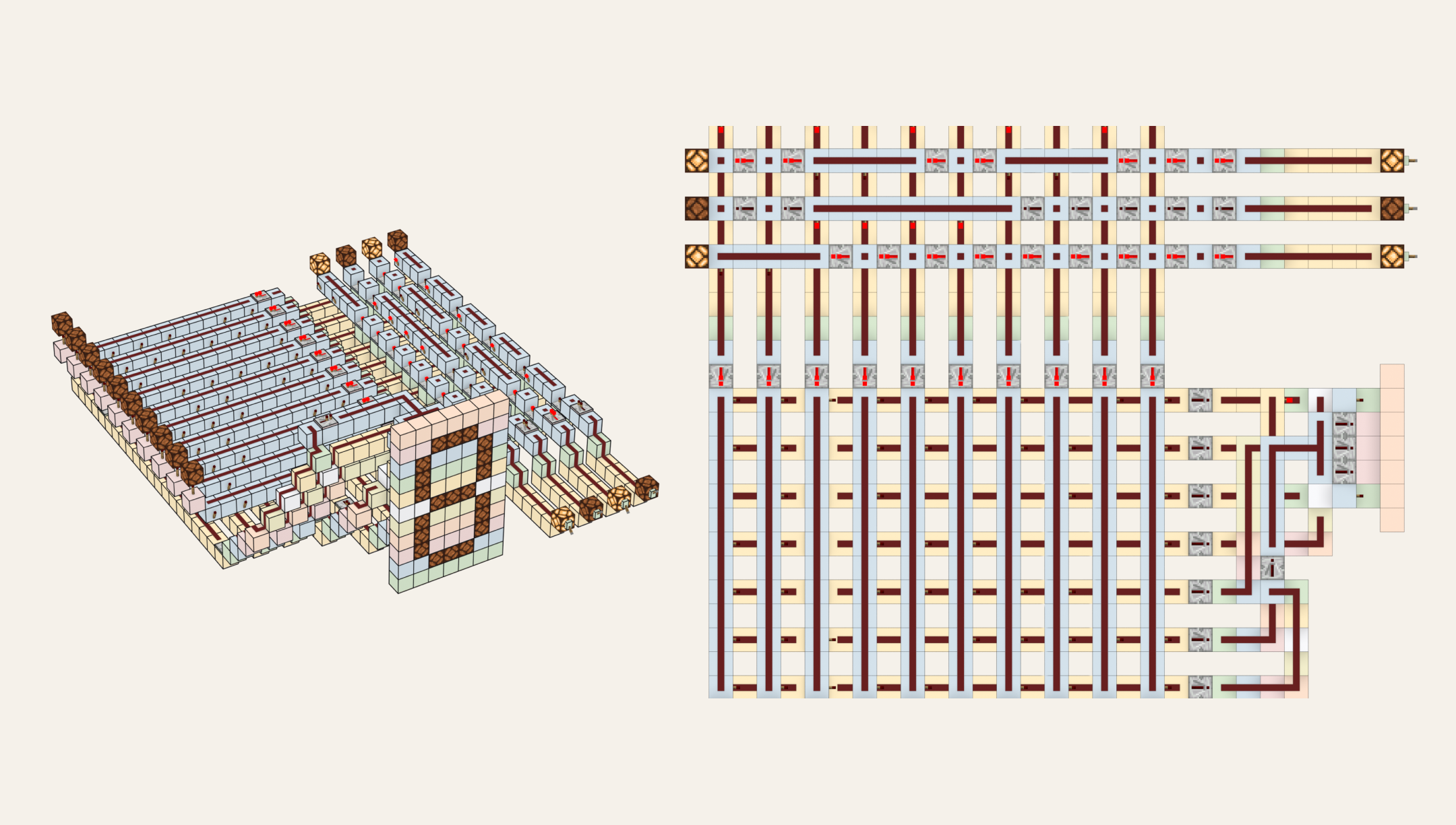
Other perspectives of the same build cost a couple of config lines, not a new pipeline. For the larger builds, a top-down view earns its keep next to the standard shot:
And camera angles are the least of it. The renderer already takes flags for cutaway slabs, for filtering blocks out of a shot, for an exploded view that floats each block layer apart so you can read what sits on what. When some future chapter needs a visualization I haven’t thought of yet, there’s a decent chance it’s one config key away.
A detail I didn’t expect to get for free: MiEx bakes the real redstone power level, 0 through 15, straight into each dust segment’s color on export. Once the renders were working, that gave me a live gradient of signal strength through the build, straight from the block states themselves, no synthetic data.
If you want the war stories
The pipeline took real time to get right, and two of the fights are worth telling.
The dust traces came out muddy for ages, and no amount of lighting work fixed them. Lighting was never the problem. I’d built everything on wool, which wasn’t a dumb choice at the time: that knit texture gives you free depth cues when you’re standing in the world taking screenshots. At figure size, the same knit reads as fine noise. Swapped the base blocks to flat white concrete and the traces just showed up. Just in time, too: the hours I’d sunk into lighting were closing in on “too damn long.”
Then there was drawing clean wire outlines onto the renders. Every texture-space trick I tried failed, because MiEx merges coplanar surfaces into single quads for performance, and a merged quad has no seams between blocks for an outline to grab onto. The fix meant abandoning texture tricks altogether: stop drawing wires onto the mesh, pull the dust positions and power levels out as data, apply Minecraft’s real connection rules, and generate the wire geometry from that topology instead. Clean corners, real slope ramps, no phantom arms, because the wires are drawn from the same adjacency logic the game itself uses. Same move as the diagrams, one level down.
Both fixes were the same move: when you’re stuck patching the wrong layer, drop down to wherever the truth actually lives and generate up from there. It took me two rounds to learn that in one project. Fool me once, shame on you. Fool me twice… in the words of President Bush, you can’t get fooled again.
Part I of the course is live at redstone.university, every figure in it generated by these two pipelines. Both live in the course repo, scripts and all, if you want to poke at them.
1,858 words · fielding